How-To: Convert To GD WRX Coil On Plug w/EJ20G ECU
Posted: Mon Sep 15, 2014 3:15 am
This is only an option if your engine uses different heads; EJ20G, EJ20H, EJ20R, and EJ25D are all known to work.
I searched far and wide for information to do this mod and found bits and pieces and even a write-up by Rob on converting a 2.5RS to later model GD WRX coil on plug (they have ignitors built-in to the coils unlike GC coils which use a single remote ignitor like our legacys) here http://forums.nasioc.com/forums/showthr ... ?t=1192028 but I was still confused. I finally figured it out with help from Rob and Josh and decided to make it easier for anyone looking to upgrade their legacy's ignition system to compliment an EJ20G ECU, Robtuned or otherwise.
You'll need to find yourself a set of coils from an 02+ WRX and make sure to get the pigtails with some wires on them to make this easier.
Remove your ignitor, or leave it. I don't think it matters. I just unplugged mine and removed it.
You'll need to add two wires to your ECU for the other two coil signals since our ECU fires them in pairs and therefore only uses two signals. For this I went to the junkyard and cut off the ECU connectors to harvest a couple pins for the empty slots on the factory harness.
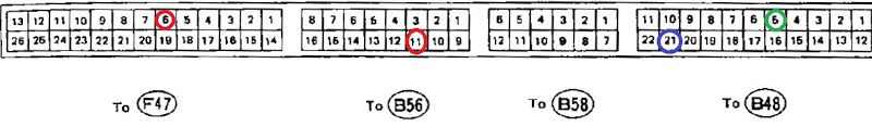
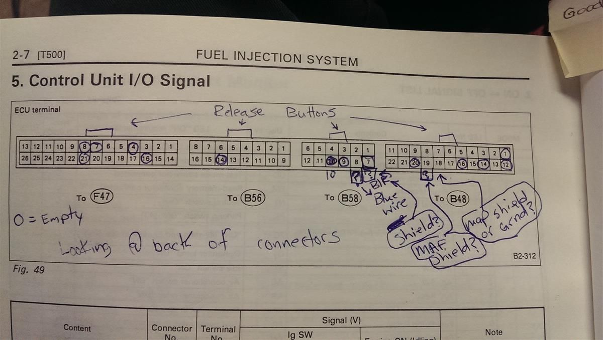
This is borrowed from one of Rob's threads : http://bbs.legacycentral.org/viewtopic. ... 62#p330762
When looking at this image your are looking at the empty ECU sockets with the release buttons on top if the plugs are inserted.
----- DE-PIN FROM CONNECTOR ------
- Purge Control (F47-6 ; White-Blue) :: Remove from the ECU plug. Purge control does not exist on the JDM EJ20G ECU. This pin is used for the 5th injector control on the WRX RAs (although it not used on any stock ECU). I am not sure what the consequence will be of losing control of the purge system.
- California Pin (B56-11 ; Green-Black) :: Remove from the ECU plug. This pin is used for the JDM EJ20G accelerator pedal switch. It has no impact on the behavior of the EJ20G ECU.
----- DE-PIN AND MERGE WITH ANOTHER ------
- MAP ground (B48-5 ; Red) :: Merge with B48-21. B48-5 is used for the stock JDM EJ20G cat efficiency EGT sensor. Not having an the stock EGT sensor has zero impact on how the ECU runs. The EJ20G harness combines the MAP sensor ground with all other sensor grounds at B48-21.
----- OTHER ECU DIFFERENCES THAT CAN BE IGNORED ------
- N/A (F47-4) :: Nothing to be done. On the EJ20G ECU, this is the Fan #2 control.
- N/A (F47-16) :: Nothing to be done. On the EJ20G ECU, this is the steering pressure switch input.
- N/A (F48-12) :: Nothing to be done. On the EJ20G ECU, this is for the EGT cat efficiency warning light.
- TPS shield (B58-7 ; Black) :: Nothing to be done. On the EJ20G ECU this pin is unpopulated in the connector. TPS shield it is located at B48-21, but B58-7 will work as well as both pins are connected inside the ECU.
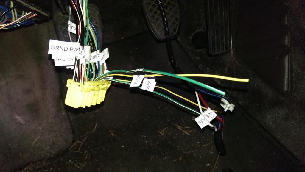
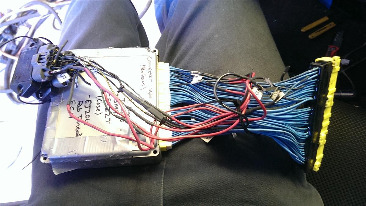
This is optional but it makes things a lot easier, not only for this job but also future trouble shooting. I labeled all my ECU wires with a Dymo labeler. Got tired of looking at the book all the time.
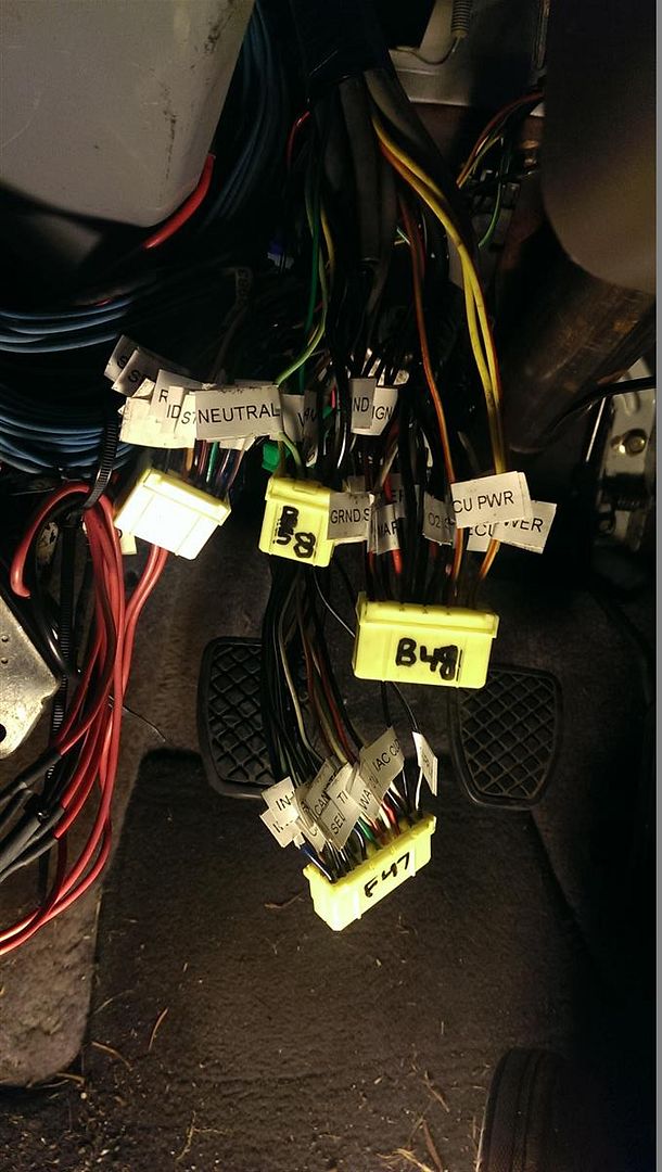
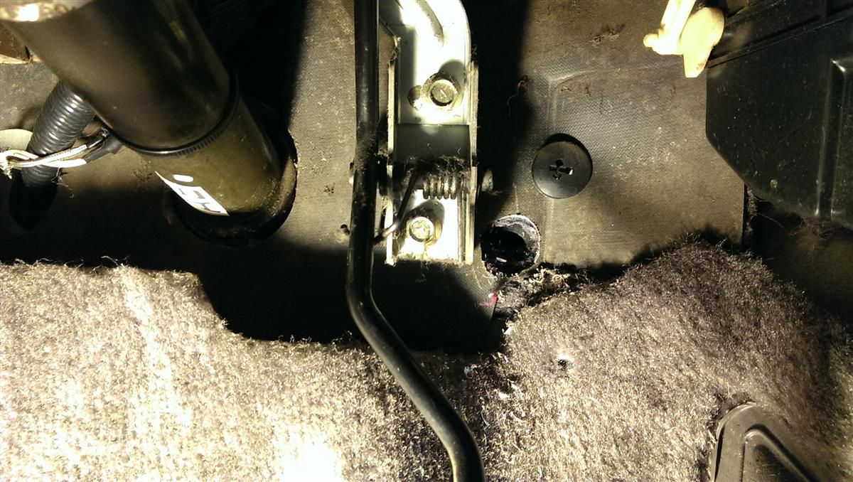
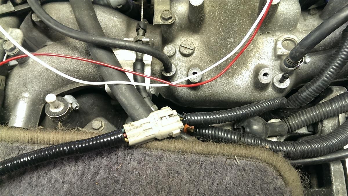
I added four new wires for the coil signals and ran them in a new harness through the firewall as shown below.
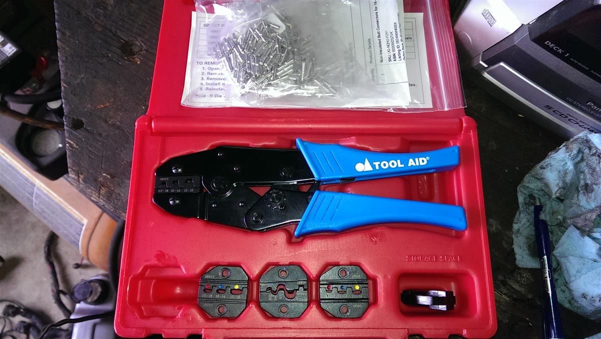
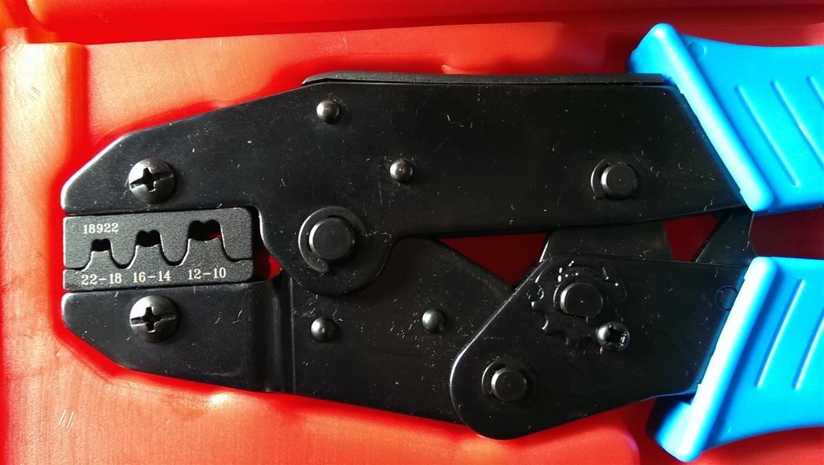
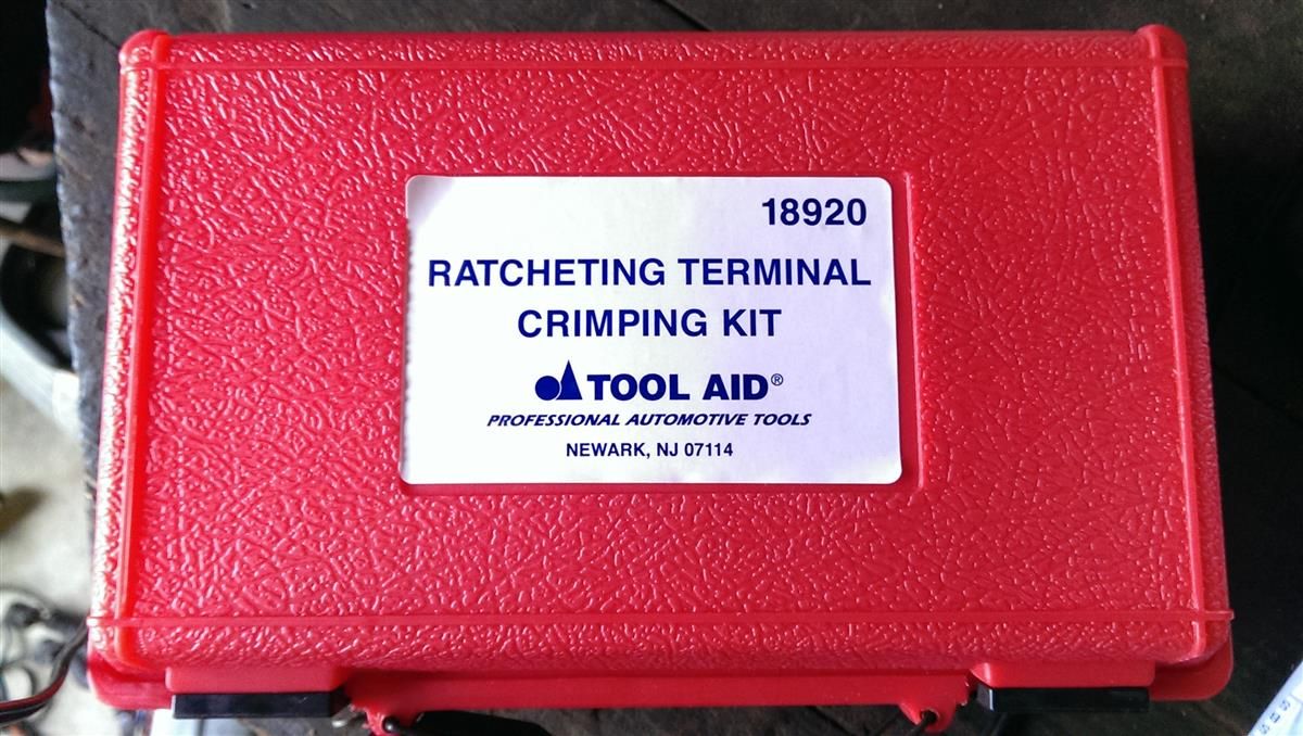
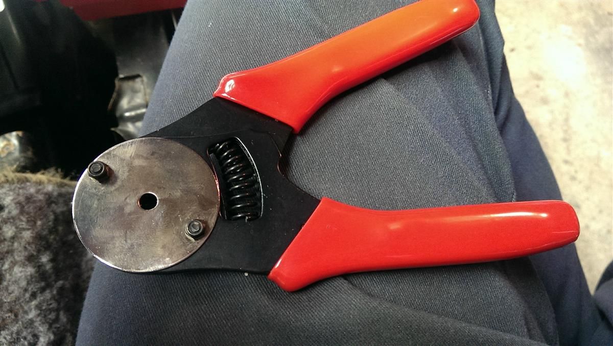
If you're new to crimping get a tool like this. S & G Tool Aid 18920 Ratcheting Terminal Crimping Kit- 5 Piece http://www.amazon.com/gp/product/B0002S ... UTF8&psc=1
You'll also want some 18-20 gauge wire and some of these uninsulated butt connectors http://www.amazon.com/gp/product/B000W2 ... UTF8&psc=1

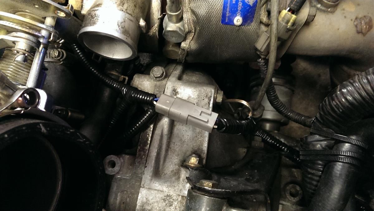
Make sure when adding the wires for the signals that you install a set of connectors to disconnect the new harness so you can easily remove your engine without ripping out the harness from your intake manifold where it should be tucked away.
I used this awesome connector - Deutsch DT Series 4 Pin Connector Kit w/Barrel Style Terminals 16-20 AWG
http://www.amazon.com/gp/product/B00D3R ... UTF8&psc=1
Here's the tool for the pins on the Deutsch connector.
http://www.amazon.com/gp/product/B003U0 ... UTF8&psc=1
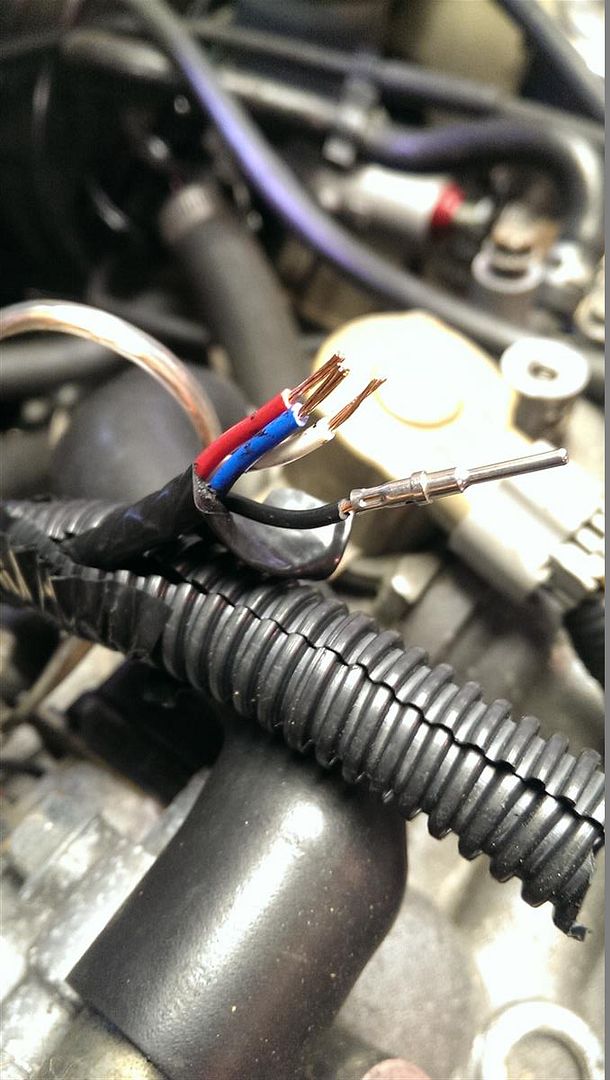
Strip the wires off like so just enough to slide into the pins and get crimped. You can crimp the pins with a crimper like the ratcheting S & G tool but it won't be as nice and you may flatten them which makes them hard to get into the connector properly.
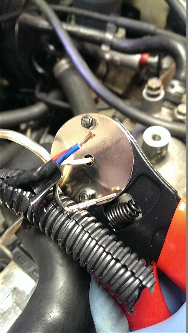
Insert the pin into the hole in the crimper and then insert the wire end into the pin pressing until you feel it bottom out and then squeeze until the crimper is closed all the way. If it releases, your crimp is finished and if not then you still need to squeeze harder for the ratcheting mechanism releases.
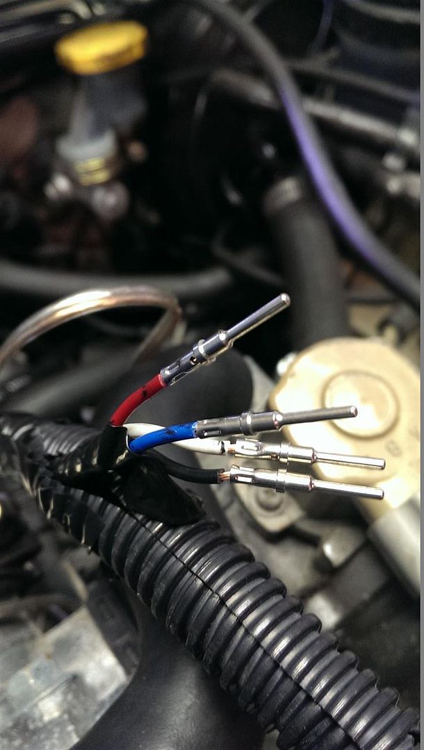
Finished pins
Insert pins with attached wires into the back of the connector's weather guard until you feel it click into place. Tug lightly to see if it is indeed seated properly. The back of the connector is numbered 1,2,3,4 which is convenient because it's a 4 cylinder. Stick them in numbered for each cylinder number and do the same on the other side of the connector and that way if you ever need to know which wire is which by the connector, just look at the ends and it's numbered for you.
This is how it looks inside the female connector with male pins in place in 2 of the 4 holes. And then with the green plug inserted after all 4 are installed. This plug holes them in place so they don't move around and it makes sure they can't come out the back.
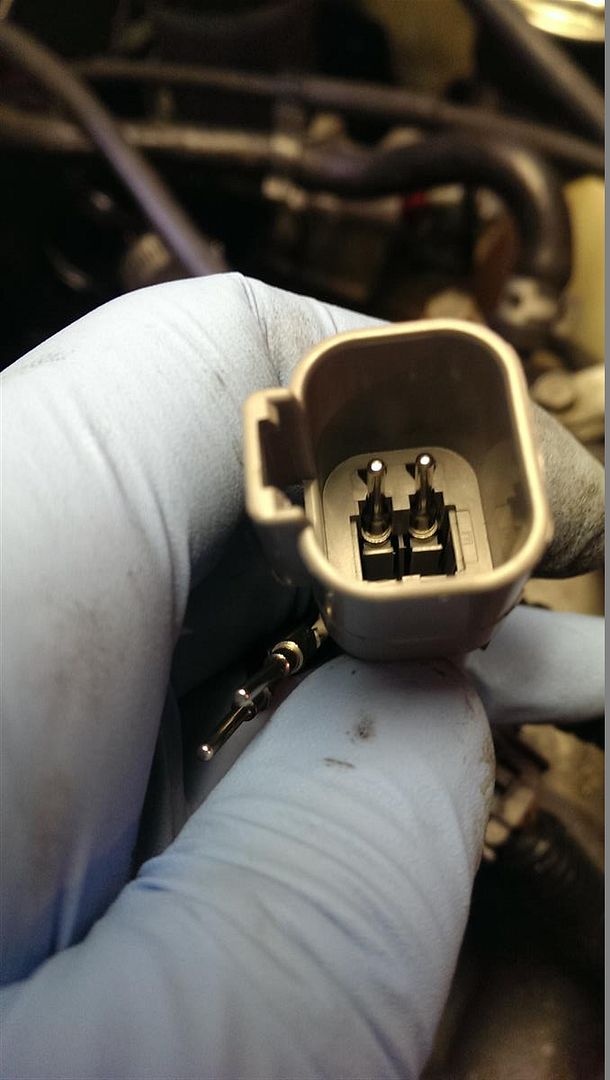
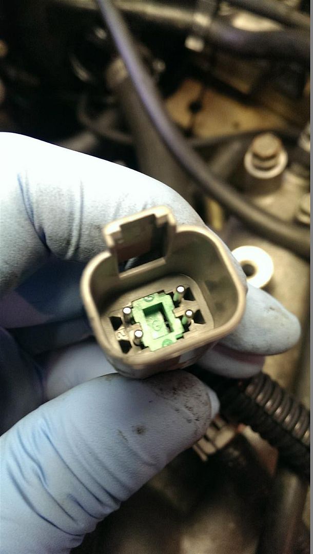
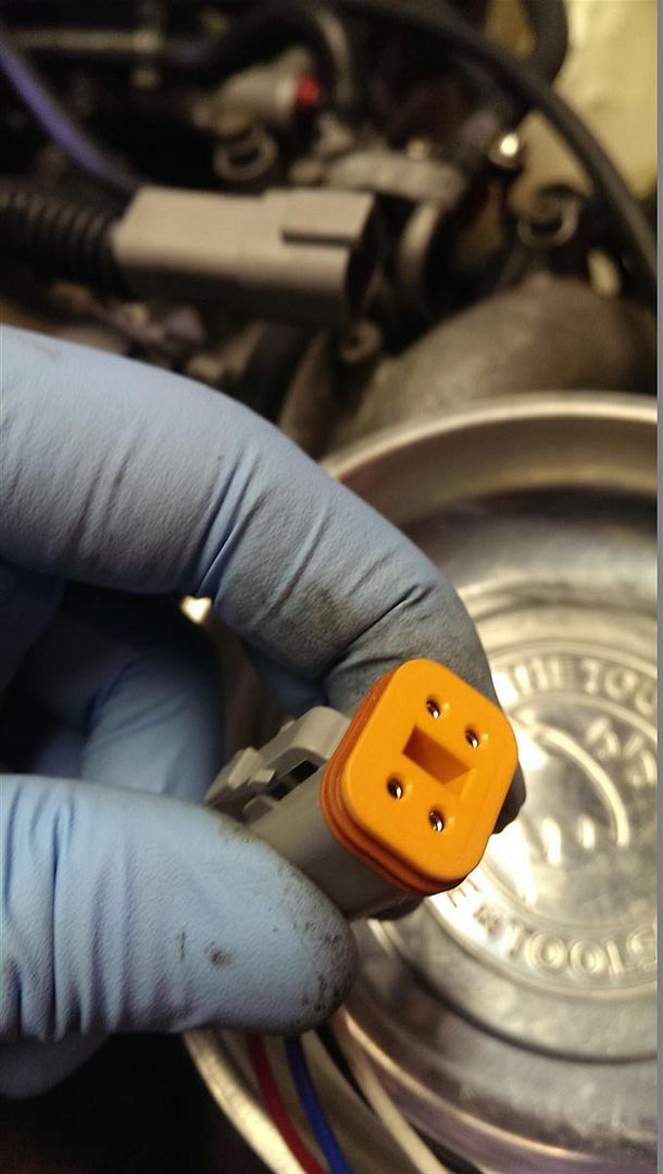
Here's a look at the male connector with female pins before and after the orange plug is inserted.
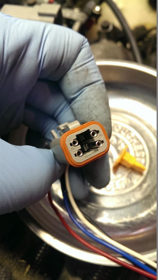
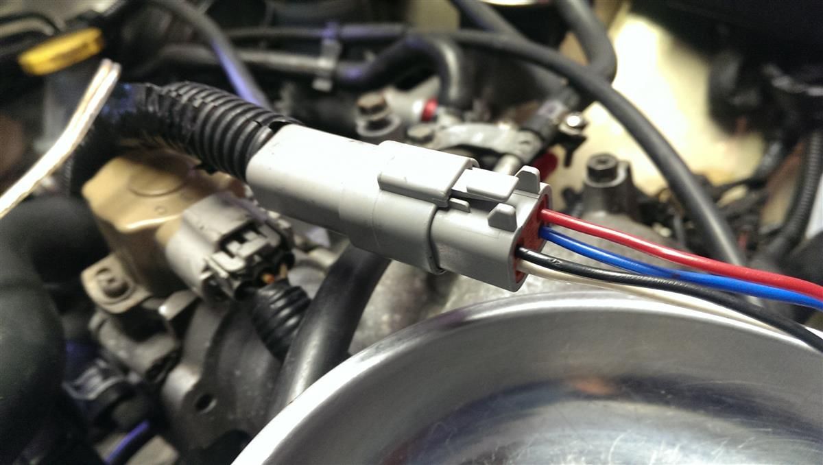
Finished connector.
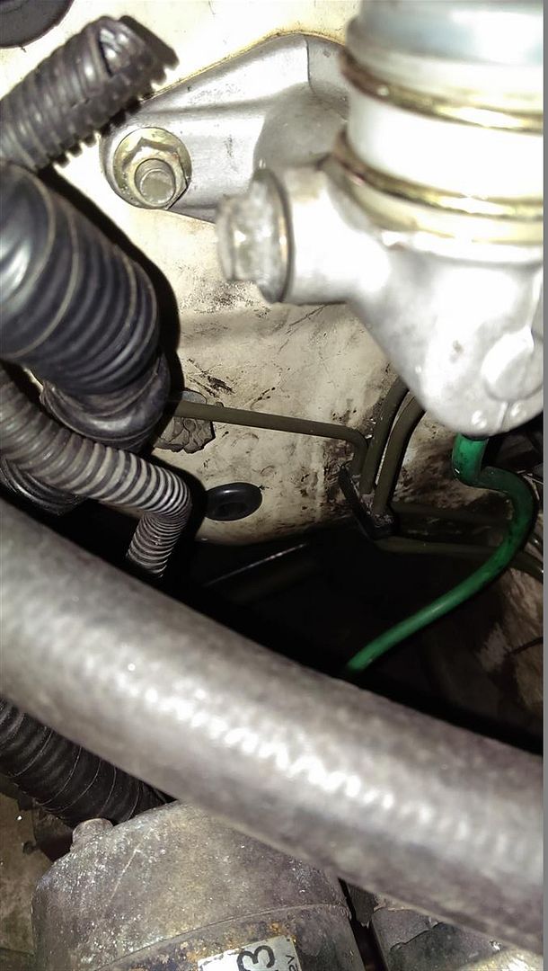
Now that you've gotten to the engine and finished your connector, before going all the way to the coils with the harness you need to get a power source. I sourced power from the harness that used to power the coil pack on top of the manifold. It's the center wire but always double check by turning you car's ignition to ON and testing for 12v at the wire. The one that has 12v out of the three is the power wire and it only has power when the ignition is on which is what you want.
I used a 14-16 gauge non-insulated butt connector for this wire because the wire was a slightly larger gauge. I hope this is ok but I'm not too sure and didn't have the same gauge wire on hand. I don't recommend you do this. Go out and get a 14-16 gauge wire so you aren't sending too much power down a lengthy inadequate set of wires like I did. Do as I say, not as I did. If my car burns down to the ground, that's on me. You've been warned.
As you can see I inserted two 20 gauge wires into the other end of the butt connector. One for each side of the engine to be split later again to each cylinder. At the time I was thinking,"This is okay because the current will be only half as much in each wire since it's split, therefore it won't be running too much current in each wire." Looking back on this now, I feel pretty stupid. Now I'm not too sure about that.
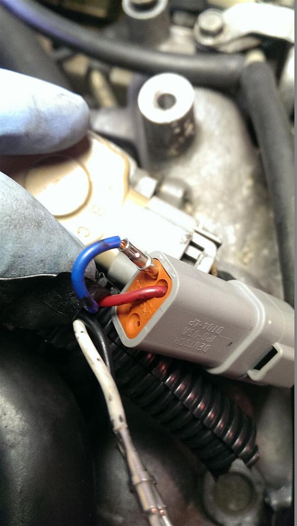
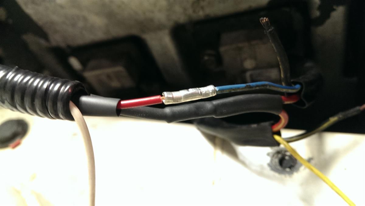
I cut off a connector from a spare coil pack I had to plug into the engine harness. Then I ran it under the manifold back to where the Deutsch connector was and merged it into that harness.
The red wires with the yellow stripes coming off the coil connectors are the power wires. Crimp the power wires you just made to them.

The other colored wire on each pigtail is the signal wire. Crimp your signal wires to the corresponding cylinders. Always put shrink tube on the wire prior to crimping or you're screwed. It's better to use marine grade 3M shrink tube that has sealant inside and seals the crimp from weather corrosion but I didn't have any at the time so I used regular shrink tube.
Use electrical tape made by 3M Scotch brand because it lasts longer, is more pliable and easier to work with and the adhesive is superior to other cheaper brands. Then slide wires into loom and electrical tape again to keep your wires fresh for years.

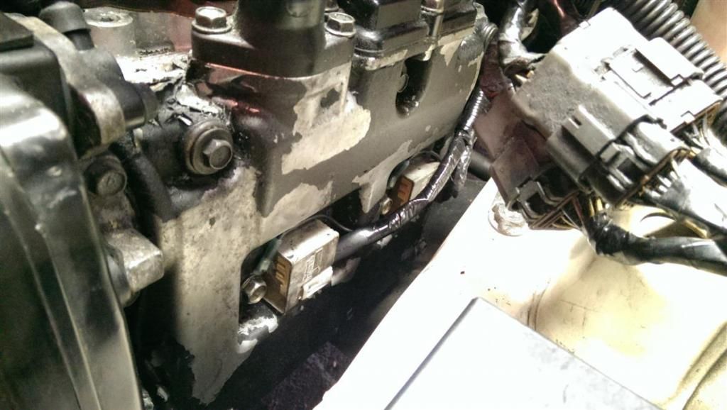
A little trick I learned while installing these coil on plugs is that cylinder #4 is a pain to get in. The frame rail is way too close to the head when you have DOHC heads. The trick I figured out was to insert it in upside down and once it's on the spark plug rotate it 180 degrees so it's right-side up.
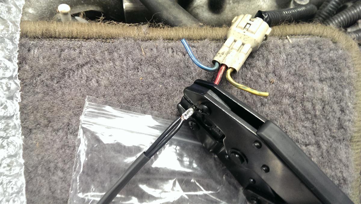
I saved the ECU signal pin wires for last. Unclip the back of the ECU plugs; both the spare that you are getting your wires/pins from and the one you're installing the new pins into. This allows removal and installation of pins. I didn't even know the plug had this feature. The first time I was trying to get the pin out without doing this with no luck. Then stick a very skinny pick inside the ECU end of the plug (I used a large needle) and run it down the side of the metal pin you are removing until it bottoms out on the plastic tab holding it in. Pry that tab away from the pin as you're gently pulling on the wire. I found it easier to push the wire in until I had the needle prying the tab away before I pulled on the wire. Otherwise it seemed like pulling on the wire made it impossible to release the tab.
Here's a video I found that makes it very easy to understand: https://www.youtube.com/watch?v=ayxEfRvhLEE
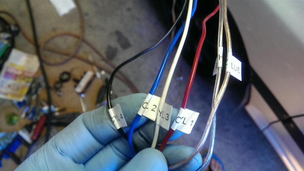
Here's the 4 signal wires installed into my harness ready to be stripped at the ends and crimped onto my new ignition harness.
Here it is finished.
Here's a picture of the factory service manual ECU pinout. Connector F47 (the far left in this picture)
Pin 10 = Cyl 1
Pin 9 = Cyl 3
Pin 8 = Cyl 2
Pin 7 = Cyl 4
If you've done all of the above wiring, your car should now fire right up. Mine did on the first try and it runs great. However, I have not had more than a few minutes to drive it so I can't tell if there's any difference in performance. I wanted to do this mod for a few reasons. To simplify my wiring harness and allow the ECU to run exactly the way it was designed and eliminate that patch harness from my list of suspects in diagnostics. To eliminate some misfiring I was having in upper RPM range on the dyno last time and hopefully allow me to open my spark gap up a bit to provide a strong spark and I was hoping these coils would provide the extra juice I was looking for but I don't know if they do or not. I had my plugs gapped around 0.026" and now they're at 0.030" which is stock gap for an STI so I feel safe with this as my starting point. It's difficult to tell without a dyno if it's fixed that upper RPM spark issue though. We'll see one day.
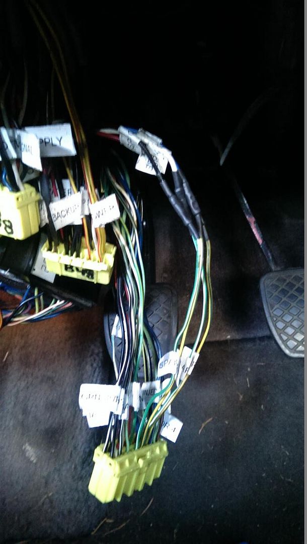
This is the patch harness I was using along with the dual ignitor conversion setup that was all crammed up under my dash. I won't be missing this mess.
Here's some more links to useful information pertaining to this mod. Thanks to Rob, Josh and VRG3 for all the help they provided me to complete this mod I've been wanting to do for years.
90-94 USDM Legacy ECU Pinout http://www.surrealmirage.com/vrg3/ecupins/
Josh's Legacy ECU Pinout spreadsheet http://main.experiencetherave.com/subar ... CU_I-O.xls
I searched far and wide for information to do this mod and found bits and pieces and even a write-up by Rob on converting a 2.5RS to later model GD WRX coil on plug (they have ignitors built-in to the coils unlike GC coils which use a single remote ignitor like our legacys) here http://forums.nasioc.com/forums/showthr ... ?t=1192028 but I was still confused. I finally figured it out with help from Rob and Josh and decided to make it easier for anyone looking to upgrade their legacy's ignition system to compliment an EJ20G ECU, Robtuned or otherwise.
You'll need to find yourself a set of coils from an 02+ WRX and make sure to get the pigtails with some wires on them to make this easier.
Remove your ignitor, or leave it. I don't think it matters. I just unplugged mine and removed it.
You'll need to add two wires to your ECU for the other two coil signals since our ECU fires them in pairs and therefore only uses two signals. For this I went to the junkyard and cut off the ECU connectors to harvest a couple pins for the empty slots on the factory harness.
This is borrowed from one of Rob's threads : http://bbs.legacycentral.org/viewtopic. ... 62#p330762
When looking at this image your are looking at the empty ECU sockets with the release buttons on top if the plugs are inserted.
----- DE-PIN FROM CONNECTOR ------
- Purge Control (F47-6 ; White-Blue) :: Remove from the ECU plug. Purge control does not exist on the JDM EJ20G ECU. This pin is used for the 5th injector control on the WRX RAs (although it not used on any stock ECU). I am not sure what the consequence will be of losing control of the purge system.
- California Pin (B56-11 ; Green-Black) :: Remove from the ECU plug. This pin is used for the JDM EJ20G accelerator pedal switch. It has no impact on the behavior of the EJ20G ECU.
----- DE-PIN AND MERGE WITH ANOTHER ------
- MAP ground (B48-5 ; Red) :: Merge with B48-21. B48-5 is used for the stock JDM EJ20G cat efficiency EGT sensor. Not having an the stock EGT sensor has zero impact on how the ECU runs. The EJ20G harness combines the MAP sensor ground with all other sensor grounds at B48-21.
----- OTHER ECU DIFFERENCES THAT CAN BE IGNORED ------
- N/A (F47-4) :: Nothing to be done. On the EJ20G ECU, this is the Fan #2 control.
- N/A (F47-16) :: Nothing to be done. On the EJ20G ECU, this is the steering pressure switch input.
- N/A (F48-12) :: Nothing to be done. On the EJ20G ECU, this is for the EGT cat efficiency warning light.
- TPS shield (B58-7 ; Black) :: Nothing to be done. On the EJ20G ECU this pin is unpopulated in the connector. TPS shield it is located at B48-21, but B58-7 will work as well as both pins are connected inside the ECU.
This is optional but it makes things a lot easier, not only for this job but also future trouble shooting. I labeled all my ECU wires with a Dymo labeler. Got tired of looking at the book all the time.
I added four new wires for the coil signals and ran them in a new harness through the firewall as shown below.
If you're new to crimping get a tool like this. S & G Tool Aid 18920 Ratcheting Terminal Crimping Kit- 5 Piece http://www.amazon.com/gp/product/B0002S ... UTF8&psc=1
You'll also want some 18-20 gauge wire and some of these uninsulated butt connectors http://www.amazon.com/gp/product/B000W2 ... UTF8&psc=1
Make sure when adding the wires for the signals that you install a set of connectors to disconnect the new harness so you can easily remove your engine without ripping out the harness from your intake manifold where it should be tucked away.
I used this awesome connector - Deutsch DT Series 4 Pin Connector Kit w/Barrel Style Terminals 16-20 AWG
http://www.amazon.com/gp/product/B00D3R ... UTF8&psc=1
Here's the tool for the pins on the Deutsch connector.
http://www.amazon.com/gp/product/B003U0 ... UTF8&psc=1
Strip the wires off like so just enough to slide into the pins and get crimped. You can crimp the pins with a crimper like the ratcheting S & G tool but it won't be as nice and you may flatten them which makes them hard to get into the connector properly.
Insert the pin into the hole in the crimper and then insert the wire end into the pin pressing until you feel it bottom out and then squeeze until the crimper is closed all the way. If it releases, your crimp is finished and if not then you still need to squeeze harder for the ratcheting mechanism releases.
Finished pins
Insert pins with attached wires into the back of the connector's weather guard until you feel it click into place. Tug lightly to see if it is indeed seated properly. The back of the connector is numbered 1,2,3,4 which is convenient because it's a 4 cylinder. Stick them in numbered for each cylinder number and do the same on the other side of the connector and that way if you ever need to know which wire is which by the connector, just look at the ends and it's numbered for you.
This is how it looks inside the female connector with male pins in place in 2 of the 4 holes. And then with the green plug inserted after all 4 are installed. This plug holes them in place so they don't move around and it makes sure they can't come out the back.
Here's a look at the male connector with female pins before and after the orange plug is inserted.
Finished connector.
Now that you've gotten to the engine and finished your connector, before going all the way to the coils with the harness you need to get a power source. I sourced power from the harness that used to power the coil pack on top of the manifold. It's the center wire but always double check by turning you car's ignition to ON and testing for 12v at the wire. The one that has 12v out of the three is the power wire and it only has power when the ignition is on which is what you want.
I used a 14-16 gauge non-insulated butt connector for this wire because the wire was a slightly larger gauge. I hope this is ok but I'm not too sure and didn't have the same gauge wire on hand. I don't recommend you do this. Go out and get a 14-16 gauge wire so you aren't sending too much power down a lengthy inadequate set of wires like I did. Do as I say, not as I did. If my car burns down to the ground, that's on me. You've been warned.
As you can see I inserted two 20 gauge wires into the other end of the butt connector. One for each side of the engine to be split later again to each cylinder. At the time I was thinking,"This is okay because the current will be only half as much in each wire since it's split, therefore it won't be running too much current in each wire." Looking back on this now, I feel pretty stupid. Now I'm not too sure about that.
I cut off a connector from a spare coil pack I had to plug into the engine harness. Then I ran it under the manifold back to where the Deutsch connector was and merged it into that harness.
The red wires with the yellow stripes coming off the coil connectors are the power wires. Crimp the power wires you just made to them.
The other colored wire on each pigtail is the signal wire. Crimp your signal wires to the corresponding cylinders. Always put shrink tube on the wire prior to crimping or you're screwed. It's better to use marine grade 3M shrink tube that has sealant inside and seals the crimp from weather corrosion but I didn't have any at the time so I used regular shrink tube.
Use electrical tape made by 3M Scotch brand because it lasts longer, is more pliable and easier to work with and the adhesive is superior to other cheaper brands. Then slide wires into loom and electrical tape again to keep your wires fresh for years.
A little trick I learned while installing these coil on plugs is that cylinder #4 is a pain to get in. The frame rail is way too close to the head when you have DOHC heads. The trick I figured out was to insert it in upside down and once it's on the spark plug rotate it 180 degrees so it's right-side up.
I saved the ECU signal pin wires for last. Unclip the back of the ECU plugs; both the spare that you are getting your wires/pins from and the one you're installing the new pins into. This allows removal and installation of pins. I didn't even know the plug had this feature. The first time I was trying to get the pin out without doing this with no luck. Then stick a very skinny pick inside the ECU end of the plug (I used a large needle) and run it down the side of the metal pin you are removing until it bottoms out on the plastic tab holding it in. Pry that tab away from the pin as you're gently pulling on the wire. I found it easier to push the wire in until I had the needle prying the tab away before I pulled on the wire. Otherwise it seemed like pulling on the wire made it impossible to release the tab.
Here's a video I found that makes it very easy to understand: https://www.youtube.com/watch?v=ayxEfRvhLEE
Here's the 4 signal wires installed into my harness ready to be stripped at the ends and crimped onto my new ignition harness.
Here it is finished.
Here's a picture of the factory service manual ECU pinout. Connector F47 (the far left in this picture)
Pin 10 = Cyl 1
Pin 9 = Cyl 3
Pin 8 = Cyl 2
Pin 7 = Cyl 4
If you've done all of the above wiring, your car should now fire right up. Mine did on the first try and it runs great. However, I have not had more than a few minutes to drive it so I can't tell if there's any difference in performance. I wanted to do this mod for a few reasons. To simplify my wiring harness and allow the ECU to run exactly the way it was designed and eliminate that patch harness from my list of suspects in diagnostics. To eliminate some misfiring I was having in upper RPM range on the dyno last time and hopefully allow me to open my spark gap up a bit to provide a strong spark and I was hoping these coils would provide the extra juice I was looking for but I don't know if they do or not. I had my plugs gapped around 0.026" and now they're at 0.030" which is stock gap for an STI so I feel safe with this as my starting point. It's difficult to tell without a dyno if it's fixed that upper RPM spark issue though. We'll see one day.
This is the patch harness I was using along with the dual ignitor conversion setup that was all crammed up under my dash. I won't be missing this mess.
Here's some more links to useful information pertaining to this mod. Thanks to Rob, Josh and VRG3 for all the help they provided me to complete this mod I've been wanting to do for years.
90-94 USDM Legacy ECU Pinout http://www.surrealmirage.com/vrg3/ecupins/
Josh's Legacy ECU Pinout spreadsheet http://main.experiencetherave.com/subar ... CU_I-O.xls