
Total installation time: ~15 hours (3 days)
Total cost: $760
Picture gallery of install
Part list
- TD05H-16G - $420
- 1x exhaust stud - $15
- 2007 WRX TMIC - $70
- Wyntonm BOV blow off adaptor - $20
- 02-05 Samco Sport Intercooler Hose Kit - $109
- 90* silicone bend (turbo to TMIC extension)
- 2” silicone sleeve connector - $16
- 2” exhaust tubing + end flairs - $20
- 7x 2” T-Bolt Clamps - $27
- 2x 3” T-Bolt Clamps - $7
- OEM Downpipe gasket - $20
- GrimmSpeed Up Pipe Gasket - $13
- 6mm x 10 x 30mm screw (secure down coolant tank) – $0.31
- 3/4” 90* elbow insert (BPV to turbo intake tube) - $0.85
- 1’ 1/2” transmission hose - $3.35
- 2’ 5/8” transmission hose - $15.76
- 4" 3/4” transmission hose - $15.18
- 6’ 5/32” vacuum hose - $4.99
- 4x Worm hose clamps - $6
Paint TMIC
While this isn’t a required mod, I decided to follow a few others from the forum since it looks cool adds some character.
- Find and download the equivalent Subaru font, "Square 721 BDex BT".
- Print out the logo you want. Seem to recall the font size was around 80. Took 2 sheets which I taped together.
- Find an old cereal box. Glue/double-side tape the logo to it. Carefully cut out the letters.

- Cut the stencil to size so it fits flush on top of the intercooler. Use painters tape and paper to cover up the intercooler.
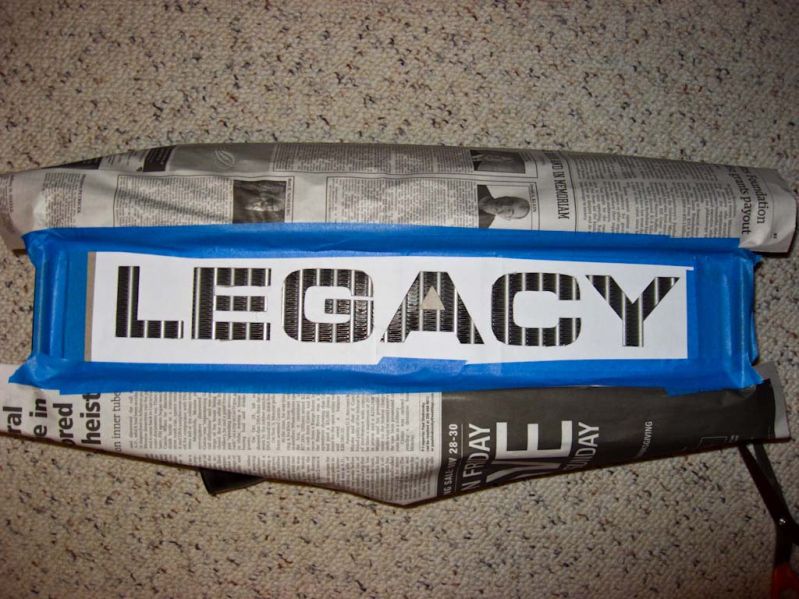
- Paint with high temp paint (like Rust-Oleum). Repeat for another coat or two. Allow time to thoroughly dry.
- Remove all the masking. Now you’ve got the finished product!

There are several ways to rig up the tubing for the intercooler, but the best (and most expensive) is to use silicone. It provides a longer lasting, more durability and flexibly during the install.
- Remove the stock y-tubing.
- The unmodified Samco y-tube doesn’t fit properly onto the 07 intercooler as seen below. Stretching the left leg to fit won’t work.

- Cut off about 1” from the left leg of the Samco y-tube. Measure twice, cut once!
- You will need to get a short piece of 2” exhaust tubing to extend the gap. Additionally, you should get a bead/lip rolled into both ends it so it creates a better seal. Mine only has one, because the machine shops tool couldn’t handle something that short. Additionally, you’ll need a ~4” section of 2” silicone tubing.

- Once all the pieces are assembled, they should all snuggly fit together.

- Next is to cut the bottom of the y-tube to extend it. While one in theory can carefully cut this portion to use the 90* at the end, it will not leave you enough silicone material for the t-clamp to bite into overtime. It’s best if you just cut the y-pipe just before the 90* and then buy a separate 90* to use. To make sure I drew/cut in a straight line, I slid a t-bolt clamp over the straight section of the tubing, Once cut, the mock up tubing will look like this. THIS IS THE OLD PICTURE WITH THE CUT TOO SHORT.

- Get another 2” piece of exhaust and cut it to ~4 3/4”. I drew lines on both ends of the metal tube, to visually see the minimum amount of tube that needed to be inserted into each end to have the proper clamping clearances. This pipe too should have rolled ends to create a better seal. Unfortunately, I found that it was too damn hard to wrangle the tube into place while in the tight constraints of the engine and had to remove them.
- Install the t-bolt clamps. Think about the location of the bolts and clearance, in case you have to access them while it’s still on the car. This is how I did it.

There are two main options for dealing with the clutch reservoir, which will be in the way of the TMIC from laying flat: cut it or get an offset one. I opted for cutting. Even with cutting though, if the engine rocks around a lot, the TMIC will still occasionally contact the top of the clutch reservoir.
- Remove the existing fluid from the reservoir. A syringe is very handy.
- Loosen the clasp around the bottom.

- Remove the empty reservoir.
- Cut the tube so it's 2" long.
- Grind/sand off any leftover plastic burs.
- Re-attach the reservoir and clamp. Re-fill with fluid.

There are various wire looms which need to be tucked under the dog bone. Additionally, those who opt to keep the A/C, can tuck the A/C line under there too.
- Unbolt both ends of the dogbone and remove.
- Loosen the wire looms from their attachments to the firewall and each other.
- Remove the bracket holding the A/C line to the perch.
- Reinstall the dogbone and tuck everything under it.

- Unscrew the igniter from its bracket on the perch. Unscrew the bracket. Unclasp the cable.
- Rough up the underside of the igniter – a stiff wire brush works well. Also do the same to the right side of the perch, where the igniter will be placed.
- Depending on the screw you use, you might have to slightly enlarge the screw hole through the igniter.
- Screw the igniter to the side of the perch mount and re-connect the cable. See the picture above for the final placement.
I found that the cruise control vacuum thingy, needed to have its mount bent in order to make room for the intercooler. Simple.
VF11 removal & TD05 install
The removal of the VF11 and install of the TD05 is fairly straight forward. Just a handful of bolts to remove and then reinstall, heh. I found it was beneficial to leave the TD05 unbolted from the downpipe (DP) and uppipe (UP), which I was mocking up the placement of various things.
- Remove the airbox and all intake tubing/lines in the area.
- Remove the 5 bolts attached to the DP. It would be beneficial to soak them with PB Blaster beforehand. Otherwise, you might twist off the head of bolt like I did
 .
. - Remove the 3 bolts attached to the UP.
- Remove the 2 coolant clamps and oil feed line. Keep that oil nut with the tubro!
- Remove the VF11 from the engine bay. Observe the gaping hole.

- Comparing the two turbos (TD05 on the left vs VF11 on right)

- Install new UP and DP gaskets. Don’t forget to clean the mating surfaces.
- Drop in the TD05. Note the F-tube and the wires going to the throttle position sensor, IAC and coilpack all interfere with the turbo’s outlet. These all need to be taken care of in time.

- Remove the F-tube. The hose and possibly plastic will crack from being brittle.
- Re-route the wires going to the TPS, IAC, coilpack so they clear the turbo output. It’s still going to be tight after you get the silicone 90* on.
- You will want to use transmission hose when re-routing all of the vacuum lines you removed. Heater hose DOES degrade over time as it gets soaked with oil and heat. I’ve had to replace most of original heater hose since this guide was created.
- Extend the f-tube from the engine. The bottom of my f-tube broke off in the process of test fitting things. Ended up sliding a larger hose over it and securing them together. More testing of locations & tube routes.
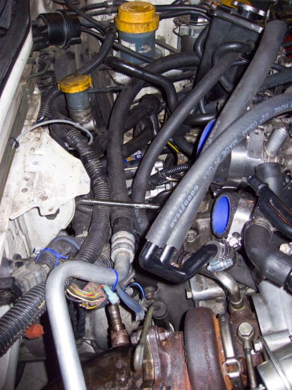
Finished engine bay post install on my other car:

- Once you’ve figured out the routing of the f-tube, then one can screw down the turbo. Bolt down the UP and DP, don’t forget to use some anti-seize compound.
- Re-attach the oil and coolant lines. The return oil line into the engine is especially tricky to get at.
The coolant tank is another item which has a wide variety of options. Those who have removed the A/C, will find the relocation process much easier. I wanted to keep my A/C, so things got a little tighter. Thankfully it was fairly easy by rotating it 90 counter-clockwise and securing it to the original mounting hole.
- Start by disconnecting all of the old coolant lines to the tank. Be ready to catch the coolant with a container.
- Turn the coolant tank 90* counter-clockwise and re-attach it to the mounting hole in the manifold. I ended up having to get a longer bolt, which was 6mmx10 x 30mm.
- The bottom coolant line (to the engine), needed to be extended.
- The middle coolant line (from the turbo), needed to be extended.
- The top coolant line (from the engine), I ended up reusing the OEM line.
- The top coolant line next to the cap, I ended up reusing the OEM line.

- Re-attach all of the various clamps to the lines.
This can be a time consuming process to properly route all of the various lines which need to be reconnected. Save yourself the hassle and go buy several feet of all the major sizes ahead of time, otherwise you’ll be on a first name basis with your local auto parts store.
- The line which attaches into the engine and the y-tube (to the 90* into the turbo on the right side), will need to be extended -- it's 1/2" about 30" long.
- The little line from the top of the F-tube, I ended up using some of the pre-bent OEM tubing (forget its original source), due to the tight bends it would have to make to get back to the 90* intake.
- The larger and bottom line from the F-tube goes directly into the intake manifold with little issue -- it's 5/8" and about 12" long.
- The large line from the 90* into the turbo (on the left side) and from the BPV, will need an extension -- it's 3/4" and 4" in length.
I bought a prefabricated BPV adaptor off eBay, which was a “Wyntonm BOV blow off adaptor”. It attaches snuggly to the intercooler. The Samco hose kit came with a hose that fits over the BOV adaptor plate, which I utilized. It’s too big to fit over the stock BPV, but if you slide it over the stock tubing and clamp it down, it makes a secure connection. I had to cut the Samco hose about 1-2” for a proper fitting so the BPV would sit next to the TPS. On the other side of the BPV, you’ll need to extend the tubing and use a 3/4” 90* elbow which goes into 90* intake to the turbo inlet. The small vacuum tube will also need to be extended from the engine.
Hood tunnel removal
Just remove the 8 screws around the parameter of hood tunnel and take it off.

Finished engine bay
(click picture for full size)

Update 2009-05-27
It's been ~5 months since I've had these upgrades installed. All of the components are still working great! I've done data logging over the past several weeks and came to the conclusion that the TD05 is too large for the stock MAF/injectors to handle -- even below fuel cut!. You WILL need engine management to run this turbo.
By now, I've got a LC-1 wideband, 440cc injectors, Autoec MAF and Revtronix Stage 2 chip installed and running ~15 PSI. The chip handles the additional components well, just make sure your O2 sensor is good, responsive and warms up quickly. Just an FYI for those thinking of going this route with upgrades.
Update 2009-07-06
I swapped my engine and performance bits from the 94 TW to 94 SS. Had to re-do some of the customizations in this guide. Also got some better pics/measurements. Guide updated.
Update 2009-09-27
Due to me cutting the Samco hose too short in the leg from the turbo (to try and save/use the 90* bend), over the past 9 months, it’s failed right at the edge and the material has been worn away. This created a major leak while on boost, but the engine still ran fine otherwise.

There was simply no material for the t-clamp to bite into. One cannot move it further up the y-tube, since it gets wider and when one tightens down the clamp, it slides down.

I decided to order a 06-07 Samco hose this time, thinking it would be a better fit on the legs of the 2007 WRX TMIC. Big mistake. The angle of the leg from the turbo to the y-pipe section is about a 45* one, instead of a 90* like the 02-05 Samco hose. Ended up having to re-order the “correct” 02-05 hose. Comparison of them both:


