

I was wondering if anyone has run across the different type of speed sensors on the newer cars. The mid-to-late 90's Subarus appeared to have two-wire speed sensors that just screw into the transmission. From what I can tell from the wiring diagrams, both wires go back up to the speedometer circuit. So I'm assuming the speedometer circuit is supplying a voltage and then reading the output signal from the speed sensor.
With the newer three wire sensors, it appears that the supply voltage is fed from a switched ignition source, another pin is ground, and the third goes to the ECU, TCU (if equipped), and the combination meter micro computer.
Interestingly enough the Liberty manual I have that shows the speed sensor separate from the combination meter shows it to have a three wire speed sensor with shielded wire.
I guess if I keep the 6spd speed sensor, I'll need to find the proper connector for it.
Three wire speed sensors vs. two wire speed sensors
Moderators: Helpinators, Moderators
Three wire speed sensors vs. two wire speed sensors
Josh
surrealmirage.com/subaru
1990 Legacy (AWD, 6MT, & EJ22T Swap)
2020 Outback Limted XT
If you need to get a hold of me please email me rather then pm
surrealmirage.com/subaru
1990 Legacy (AWD, 6MT, & EJ22T Swap)
2020 Outback Limted XT
If you need to get a hold of me please email me rather then pm
Re: Three wire speed sensors vs. two wire speed sensors
I'm not sure about the years, but I noticed when researching the speed sensor on my '98 Outback that manual transmission cars use a different sensor then automatic cars. The manuals has a sensor with a pigtail to the harness connector while the autos had the harness plug directly into the sensor.
I'm not sure how many wires, but maybe that helps. First gen overseas Legacy/Liberties had electric speedos on some models (possibly all?)
I'm not sure how many wires, but maybe that helps. First gen overseas Legacy/Liberties had electric speedos on some models (possibly all?)
'93 Winestone SS Auto, '91 Pearl White SS.
'93 Pure White SS EJ20G slanty intercooled, SIDESWIPED! In stasis.
'94 FWD and '95 AWD Laguna Blue SVXs.
2017 Pure Red BRZ Limited w/Performance pack
'93 Pure White SS EJ20G slanty intercooled, SIDESWIPED! In stasis.
'94 FWD and '95 AWD Laguna Blue SVXs.
2017 Pure Red BRZ Limited w/Performance pack
Re: Three wire speed sensors vs. two wire speed sensors
Thanks for the feedback PhyrraM.
From the research I've done, only the turbo models overseas had the electronic speedos. I ended up snagging one from the UK and will be putting it in my Legacy.
From the research I've done, only the turbo models overseas had the electronic speedos. I ended up snagging one from the UK and will be putting it in my Legacy.
Josh
surrealmirage.com/subaru
1990 Legacy (AWD, 6MT, & EJ22T Swap)
2020 Outback Limted XT
If you need to get a hold of me please email me rather then pm
surrealmirage.com/subaru
1990 Legacy (AWD, 6MT, & EJ22T Swap)
2020 Outback Limted XT
If you need to get a hold of me please email me rather then pm
Re: Three wire speed sensors vs. two wire speed sensors
I'm guessing the two wire one is similar to bicycle speedometer sensor. Reed switch. Like the VSS used within the instrument cluster. It basically opens and closes the contacts each time the magnet fly by and faster it is, the more pulses you get per minute.
The output is then outputted into meter by A/D converter.. or considering the age of our cars maybe an analog integrator.
The 3 wire one could be providing the same output via solid state switch or it could be a module that generates pulse.
Either way, its not hard to convert the signal. If it's putting out voltage, put it through a transistor and you'll have an open-collector output which you could then mate with traditional system.
Re: Three wire speed sensors vs. two wire speed sensors
I'm tacking on to this thread because I'm up against this issue with my Vanagon conversion project. I have a 2006 Impreza 5MT transmission with an integral 3 wire VSS. I need to adapt the 3 wire VSS system to the 91-94 OBD1 legacy system which receives its vehicle speed via a speedometer reed switch which simply connects ECU pin B11 to ground. My plan is to connect ignition switched power and ground to the 3 wire VSS and then use the VSS pulse output to control an NPN transistor. If I understand the open collector concept, I'll connect the VSS pulse output to the NPN transistor base, the NPN collector to ECU pin B11 and the NPN emitter to ground. Do I have that right?
From what I've found online, the Subaru 3 wire VSS is generating the pulse output via a rotating magnetic resistance element which means that the square wave output is going to have a high voltage at something less than ignition voltage and a low voltage at something slightly above 0V. Does anyone know what those max/min voltage values are assuming a +12V to +14V ignition power source? If not, no big deal, I'll find out with an oscilloscope down the road. But I'll need to know those voltages so that I can select a transistor with a gate threshold voltage less than than the max VSS pulse but greater than the minimum VSS pulse. Make sense?
From what I've found online, the Subaru 3 wire VSS is generating the pulse output via a rotating magnetic resistance element which means that the square wave output is going to have a high voltage at something less than ignition voltage and a low voltage at something slightly above 0V. Does anyone know what those max/min voltage values are assuming a +12V to +14V ignition power source? If not, no big deal, I'll find out with an oscilloscope down the road. But I'll need to know those voltages so that I can select a transistor with a gate threshold voltage less than than the max VSS pulse but greater than the minimum VSS pulse. Make sense?
1987 VW Westfalia Vanagon - EJ22T Powered
1994 Legacy Touring Wagon
1994 Legacy Touring Wagon
Re: Three wire speed sensors vs. two wire speed sensors
Maybe I'm missing something, but why do you need the NPN transistor? Is that so the output works with the vanagon speedometer? Based on the data I see in the FSM the output from the speed sensor is changing between 0v and 5v.
Josh
surrealmirage.com/subaru
1990 Legacy (AWD, 6MT, & EJ22T Swap)
2020 Outback Limted XT
If you need to get a hold of me please email me rather then pm
surrealmirage.com/subaru
1990 Legacy (AWD, 6MT, & EJ22T Swap)
2020 Outback Limted XT
If you need to get a hold of me please email me rather then pm
Re: Three wire speed sensors vs. two wire speed sensors
Not worried about the speedometer. The newer VSS outputs a square wave that has a max voltage greater than 5V. I want to use the new VSS signal but I'm weary of connecting that VSS output directly to the ECU because we know that our older ECUs are designed to have only 5V on pin B11.
1987 VW Westfalia Vanagon - EJ22T Powered
1994 Legacy Touring Wagon
1994 Legacy Touring Wagon
Re: Three wire speed sensors vs. two wire speed sensors
Have you tested the output signal from the VSS to see if it's actually higher than 5v? If so, how much higher is it.
Again, the info I saw in the factory manual for the newer VSS shows 0 & 5v being what is inputted to the ECU. There was no modification of that signal between the VSS and ECU.
Again, the info I saw in the factory manual for the newer VSS shows 0 & 5v being what is inputted to the ECU. There was no modification of that signal between the VSS and ECU.
Josh
surrealmirage.com/subaru
1990 Legacy (AWD, 6MT, & EJ22T Swap)
2020 Outback Limted XT
If you need to get a hold of me please email me rather then pm
surrealmirage.com/subaru
1990 Legacy (AWD, 6MT, & EJ22T Swap)
2020 Outback Limted XT
If you need to get a hold of me please email me rather then pm
Re: Three wire speed sensors vs. two wire speed sensors
Interesting. I have not tested it yet, but I will before deciding on the appropriate next step. Do you know if the supply voltage to the newer three wire VSS is +12V ignition switched power?
1987 VW Westfalia Vanagon - EJ22T Powered
1994 Legacy Touring Wagon
1994 Legacy Touring Wagon
Re: Three wire speed sensors vs. two wire speed sensors
Found the 2006 FSM wiring diagram and I'm seeing that new VSS does indeed output a 5V square wave using 12V ignition sourced power and ground. I still don't think that it would be best practice to connect the newer VSS output directly to the older ECU speed sensor pin since the ECU is already outputting 5V and expecting a switched low impedance ground path. But, it's tempting to just try it and see if it works.
Knowing that I have a 5V VSS control signal to interface with is still progress. I'll report back once I get this drivetrain spinning and can do some testing.
Knowing that I have a 5V VSS control signal to interface with is still progress. I'll report back once I get this drivetrain spinning and can do some testing.
1987 VW Westfalia Vanagon - EJ22T Powered
1994 Legacy Touring Wagon
1994 Legacy Touring Wagon
Re: Three wire speed sensors vs. two wire speed sensors
I would give it a try and see how it works. I just checked my Link ECU to see how it's setup and I have the pull up resistor enabled. I'm not 100% sure whether that is still enabled from when I had the original reed switch speedometer or not. Either way the speedo input to the ECU works with the pull up resistor turned on, which is more or less how the stock ECU is setup.
Josh
surrealmirage.com/subaru
1990 Legacy (AWD, 6MT, & EJ22T Swap)
2020 Outback Limted XT
If you need to get a hold of me please email me rather then pm
surrealmirage.com/subaru
1990 Legacy (AWD, 6MT, & EJ22T Swap)
2020 Outback Limted XT
If you need to get a hold of me please email me rather then pm
Re: Three wire speed sensors vs. two wire speed sensors
I have this one verified.
Short answer: The 3 wire VSS output pin can be connected directly to pin B11 on our 91 to 94 ECUs
Explanation and Testing:
The 3 wire speed sensor takes +12V power and ground and outputs an alternating low resistance/high resistance pulse. With the VSS output disconnected from the ECU, the output during the high resistance portion of the cycle is about 1.5V. During the low resistance portion, it's in the milivolt range. So the VSS itself does not output +5V. I verified this operation using my oscilloscope.
The ECU outputs +5V continuously and "waits" for the VSS to pull the ECU down to near-zero during the low resistance portions of one complete revolution.
When the VSS output is connected to the ECU speed sensing pin and the signal is probed again, now you can see the square wave oscillating between +5V and about 150mV.
For reference, on the connector that plugs into the VSS:
Pin 1=Output
Pin 2=Ground
Pin 3=+12V
The wire colors used for pins 1 and 3 seem to vary over the model years. Don't trust the colors! Verify the wire colors to pins 1 and 3 before connecting power.
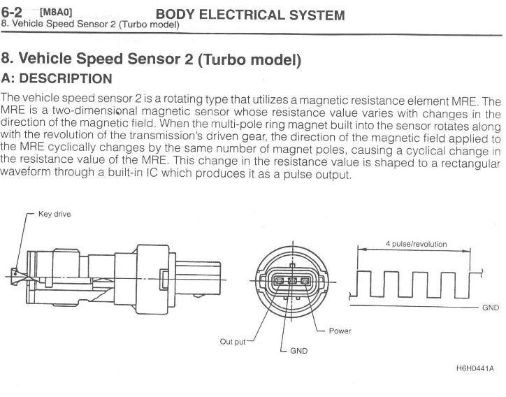
The snip below explains the VSS sensor operation. It's important to note that the alternating magnetic reluctance devise output is buffered by an internal integrated timer circuit which "latches" low/high to generate the square wave needed by the ECU. A MRE alone would generate a more sinusoidal output.
VSS Operational Description:
2006 Impreza 2.5i VSS Wiring Diagram:
https://drive.google.com/file/d/1y5jPJT ... sp=sharing
Short answer: The 3 wire VSS output pin can be connected directly to pin B11 on our 91 to 94 ECUs
Explanation and Testing:
The 3 wire speed sensor takes +12V power and ground and outputs an alternating low resistance/high resistance pulse. With the VSS output disconnected from the ECU, the output during the high resistance portion of the cycle is about 1.5V. During the low resistance portion, it's in the milivolt range. So the VSS itself does not output +5V. I verified this operation using my oscilloscope.
The ECU outputs +5V continuously and "waits" for the VSS to pull the ECU down to near-zero during the low resistance portions of one complete revolution.
When the VSS output is connected to the ECU speed sensing pin and the signal is probed again, now you can see the square wave oscillating between +5V and about 150mV.
For reference, on the connector that plugs into the VSS:
Pin 1=Output
Pin 2=Ground
Pin 3=+12V
The wire colors used for pins 1 and 3 seem to vary over the model years. Don't trust the colors! Verify the wire colors to pins 1 and 3 before connecting power.
The snip below explains the VSS sensor operation. It's important to note that the alternating magnetic reluctance devise output is buffered by an internal integrated timer circuit which "latches" low/high to generate the square wave needed by the ECU. A MRE alone would generate a more sinusoidal output.
VSS Operational Description:
2006 Impreza 2.5i VSS Wiring Diagram:
https://drive.google.com/file/d/1y5jPJT ... sp=sharing
1987 VW Westfalia Vanagon - EJ22T Powered
1994 Legacy Touring Wagon
1994 Legacy Touring Wagon
Re: Three wire speed sensors vs. two wire speed sensors
Thanks for the detailed reply and information. I guess just to confirm and make sure I understand correctly.....you're saying that you could hook up one wire to the output pin of the 3-wire VSS and that would work with the 90-94 ECU's and what they expect to see from the VSS input pin?
I am not clear whether the power and ground need to be hooked up to the 3-wire VSS.
Thanks
I am not clear whether the power and ground need to be hooked up to the 3-wire VSS.
Thanks
Josh
surrealmirage.com/subaru
1990 Legacy (AWD, 6MT, & EJ22T Swap)
2020 Outback Limted XT
If you need to get a hold of me please email me rather then pm
surrealmirage.com/subaru
1990 Legacy (AWD, 6MT, & EJ22T Swap)
2020 Outback Limted XT
If you need to get a hold of me please email me rather then pm
-
stevieturbo
- In Neutral
- Posts: 7
- Joined: Fri Aug 30, 2013 11:16 pm
- Location: Norn Iron, UK
Re: Three wire speed sensors vs. two wire speed sensors
I've never seen a 2 wire speed trigger on a Subaru manual trans ?
They're all 3 wire, 12v, signal and ground, digital.
Such a sensor will always need power and ground in order to provide an output.
They're all 3 wire, 12v, signal and ground, digital.
Such a sensor will always need power and ground in order to provide an output.
-
cj91legss
- Fifth Gear
- Posts: 6322
- Joined: Fri Jun 20, 2008 8:17 am
- Location: Lakewood, Wa 98439
- Contact:
Re: Three wire speed sensors vs. two wire speed sensors
There are 2 wire sensors. Early impreza and second gen legacy had them for a short time.
91 L-TW Wagon with a full Swap -RIP
92 SS Prefaced, GD dash swapped, 22T/205 Hybrid 20 psi - BEAST!
93 SS Bone Stock Gone!
94 TW Bone Stock Gone!
91 SS 4EAT Sold!
98 LGT 4EAT
98 LGT Wagon 4EAT
92 SS Prefaced, GD dash swapped, 22T/205 Hybrid 20 psi - BEAST!
93 SS Bone Stock Gone!
94 TW Bone Stock Gone!
91 SS 4EAT Sold!
98 LGT 4EAT
98 LGT Wagon 4EAT
-
Bcaron1000
- First Gear
- Posts: 68
- Joined: Thu Jul 27, 2017 6:05 am
Re: Three wire speed sensors vs. two wire speed sensors
Hey guys, so this post I found pretty helpful for something I was doing, I installed a haltech ic7 dash in my legacy and had to find a solution for a speed sensor. I grabbed a three wire speed sensor from the local scrap yards and followed the diagram above. If you ever need to do this just remember the 12v power supply for the sensor should actually be a 5v power supply, too much power doesn’t work. Just an experience I encountered this afternoon.
Here’s the dash I installed

Sent from my iPhone using Tapatalk
Here’s the dash I installed

Sent from my iPhone using Tapatalk
Re: Three wire speed sensors vs. two wire speed sensors
Looks pretty awesome! I'm guessing you need their ECU to use something like that right?
Can you elaborate on the 12v being too much as that's the proper voltage at least for the three wire sensor I'm using for my 6spd swap and electronic gauge cluster.
Can you elaborate on the 12v being too much as that's the proper voltage at least for the three wire sensor I'm using for my 6spd swap and electronic gauge cluster.
Josh
surrealmirage.com/subaru
1990 Legacy (AWD, 6MT, & EJ22T Swap)
2020 Outback Limted XT
If you need to get a hold of me please email me rather then pm
surrealmirage.com/subaru
1990 Legacy (AWD, 6MT, & EJ22T Swap)
2020 Outback Limted XT
If you need to get a hold of me please email me rather then pm
-
Bcaron1000
- First Gear
- Posts: 68
- Joined: Thu Jul 27, 2017 6:05 am
Re: Three wire speed sensors vs. two wire speed sensors
Well I tried 12 volts ran to a 3 wire speed sensor, and it wouldn’t display any output from the “Hall effect” sensor within the 3 wire speed sensor. A 5 volt power supply fixed that issue. Have you pulled the plug on your speed sensor and took the value of voltage from power supply wire to your speed sensor using a multimeter? Does it really read 12volts? Just weird it didn’t work for me if that’s the case.
You can actually use these dashes as a “standalone” just to display all temps but it take a bit of wiring to figure out. Having a ecu to go with it definitely makes it easier.
Sent from my iPhone using Tapatalk
You can actually use these dashes as a “standalone” just to display all temps but it take a bit of wiring to figure out. Having a ecu to go with it definitely makes it easier.
Sent from my iPhone using Tapatalk
Re: Three wire speed sensors vs. two wire speed sensors
I haven't checked the voltage and it's been so long since I put it in I'd have to dig and double check things to see exactly how I did the wiring.
Did your ECU have a configuration to adjust the digital input settings and to turn on/off the pull up resistor and adjust the active edge? My digital input is setup with the pull up resistor on and active edge set to rising.
So in theory I could use that dash with my Link ECU?
Did your ECU have a configuration to adjust the digital input settings and to turn on/off the pull up resistor and adjust the active edge? My digital input is setup with the pull up resistor on and active edge set to rising.
So in theory I could use that dash with my Link ECU?
Josh
surrealmirage.com/subaru
1990 Legacy (AWD, 6MT, & EJ22T Swap)
2020 Outback Limted XT
If you need to get a hold of me please email me rather then pm
surrealmirage.com/subaru
1990 Legacy (AWD, 6MT, & EJ22T Swap)
2020 Outback Limted XT
If you need to get a hold of me please email me rather then pm
-
Bcaron1000
- First Gear
- Posts: 68
- Joined: Thu Jul 27, 2017 6:05 am
Re: Three wire speed sensors vs. two wire speed sensors
Yeah you should be able to
Sent from my iPhone using Tapatalk
Sent from my iPhone using Tapatalk
Re: Three wire speed sensors vs. two wire speed sensors
Coolio! Good to know.
Josh
surrealmirage.com/subaru
1990 Legacy (AWD, 6MT, & EJ22T Swap)
2020 Outback Limted XT
If you need to get a hold of me please email me rather then pm
surrealmirage.com/subaru
1990 Legacy (AWD, 6MT, & EJ22T Swap)
2020 Outback Limted XT
If you need to get a hold of me please email me rather then pm